Drawing plane definition engineering ~ Cutting Plane Lines are long lines thickened ar ends and thin elsewhere with alternately long and short dashes of proportion ranging from 41 to 61 and evenly spaced. What are reference planes and what is their use in engineering drawing. Indeed recently is being searched by consumers around us, perhaps one of you personally. Individuals now are accustomed to using the internet in gadgets to view video and image information for inspiration, and according to the name of this article I will discuss about Drawing Plane Definition Engineering Isometric drawing or isometric view 1 Section plane parallel to the base of the pyramid 2 Section plane parallel to the VP.
Source Image @ www.slideshare.net
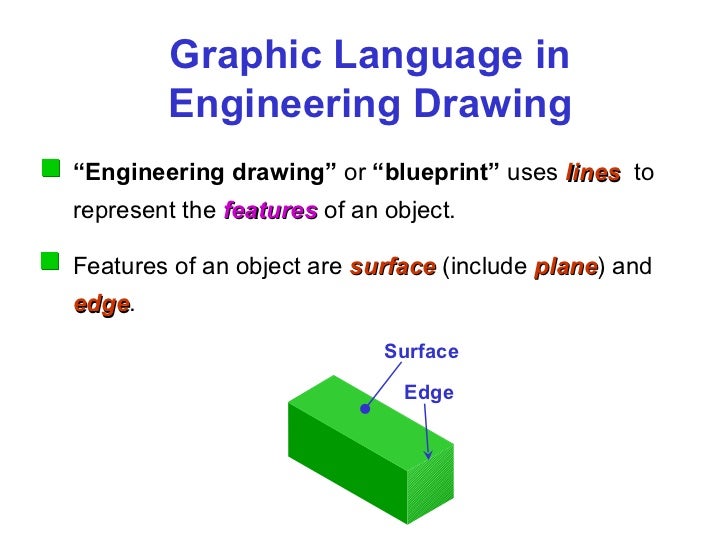
Engineering Drawing Chapter 01 Introduction

The corners where the section plane charges the direction are made thick for a short length. Years ago they were done by pencil on a drafting table but now engineering drawings are done on a computer. Your Drawing plane definition engineering image are available in this site. Drawing plane definition engineering are a topic that is being searched for and liked by netizens today. You can Find and Download or bookmark the Drawing plane definition engineering files here
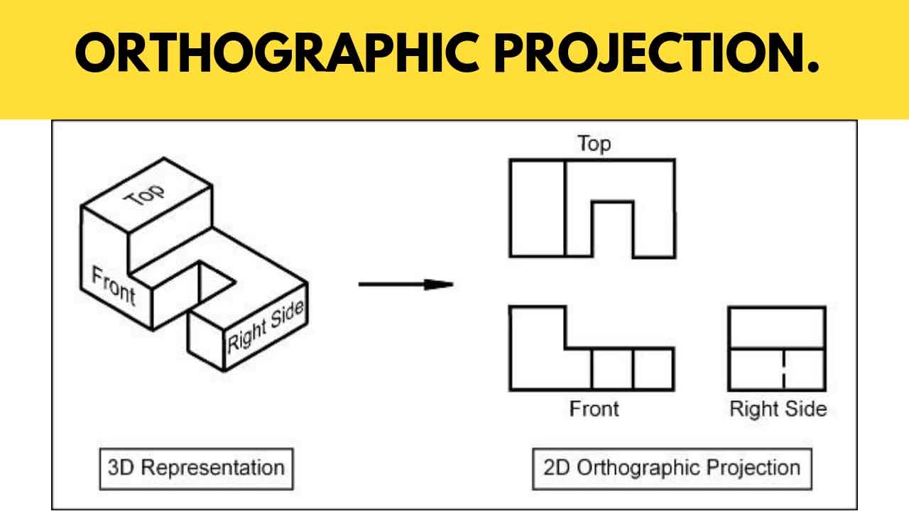
Drawing plane definition engineering - Orthographic projection technique can produce either pictorial drawings that show all three dimensions of an object in one view or multi-views that show only two. Isometric drawing or isometric view 1 Section plane parallel to the base of the pyramid 2 Section plane parallel to the VP. Engineering drawings are defined as those drawings that communicate the requirements for the manufacture of the end-product items their assembly and their installation in the end product. This will define the plane that you want to use for the front view.
Engineering drawings are those drawings that are used on the shopfloor to improve productivity. Notice that the part appears in the drawing window and you have a blue orientation circle in. The idea is drawn on a sheet by using point line and other drawing entities to give complete information or complete detail about the idea. DRAW RHOMBUS OF 100 MM 70 MM LONG BY RHOMBUS METHOD DIAGONALS AND INSCRIBE AN ELLIPSE IN IT.
-A radius draw an arc AB. This is especially true for the engineer. Horizontal plane Vertical plane in detailed explanationEngineering Drawing for first. Engineering drawing generally means technical drawings made by engineers and drafters intended for construction or manufacturing.
Cutting Plane Lines. Engineering Drawing Lecture 8 22-08-2011 1 Projection of Planes Indian Institute of Technology Guwahati Guwahati 781039. Select the plane shown below from the part. FIGURE PART OR LOCAL SECTIONS Part at a to detail of type u normal the maln m drawings in this THE FULL SECTIONAL VIEW the d FIGURE 310 ALIGNED SECTIONS In to detail a plane a is 12 an eric of a which cut and apart.
32 Drawing sectional views In orthogonal to complete of an ng Intemally of a The of C line to Nhlch it The of a lire type A. FIGURE PART OR LOCAL SECTIONS Part at a to detail of type u normal the maln m drawings in this THE FULL SECTIONAL VIEW the d FIGURE 310 ALIGNED SECTIONS In to detail a plane a is 12 an eric of a which cut and apart. Each type is defined by general description application guide lines and specific content requirements. An engineering drawing is a type of technical drawing that is used to convey information about an object.
Thin Chain Line with Thick ends. In our illustration it is a simple task to draw the. Drawing usually means using drawing instruments from compasses to computers to bring precision to the drawings. Work on this Standard considered the types of engineering drawings most frequently used by business industry and government com.
Answer 1 of 2. Usually a number of drawings are necessary to completely specify even a simple component. A common use is to specify the geometry necessary for the construction of a component and is called a detail drawing. Isometric graph 3 Section plane perpendicular to.
Isometric graph 3 Section plane perpendicular to the VP. The diagram shown below should appear in your drawing window. Lines to indicate Surfaces which require Additional Treatment. The purpose of this guide is to give you the basics of engineering sketching and drawing.
This Standard was prepared to define the accepted drawing types used to establish engineering requirements. The drawings are linked together by a master drawing or assembly drawing which gives. T he Picture Plane is the flat two-dimensional surface on which we draw or project an image in perspective. This will allow you to define a plane from a 3D object and create the front view.
Draw rhombus of given dimensions. 32 Drawing sectional views In orthogonal to complete of an ng Intemally of a The of C line to Nhlch it The of a lire type A. Mark points 1234 as four centers. The Thin Chain Line is used to indicate center lines the lines of symmetry and also trajectories.
This helps to identify the plane in which the part or assembly is cut. A parallel projection technique in which the plane of projection is perpendicular to the parallel line of sight. Join these points to the ends of smaller diagonals. Horizontal plane Vertical plane in detailed explanationEngineering Drawing for first year - YouTube.
What is Projection Projectors and Plane of Projection Engineering Drawing Fly Rajputs - YouTube. We will treat sketching and drawing as one. Engineering Drawing is the universal language of engineers. 1 Fundamental of Engineering Instruments and practice of drawing lines 1101 - 1309 18 Hrs 2 Geometrical figures lettering numbering and method of dimensioning 1410 - 1618 18 Hrs 3 Free hand drawing 1719 - 1723 6 Hrs 4 Drawing sheet sizes title block and item list 1824 6 Hrs.
Take 2 as center draw an arc CD. Mark mid points of all sides name Those ABC D 3. What is Projection Projectors and Plane of Projection Engineering Drawing Fly Rajputs. Sectional cutting planes are indicated with a Thin Chain Line with Thick ends.
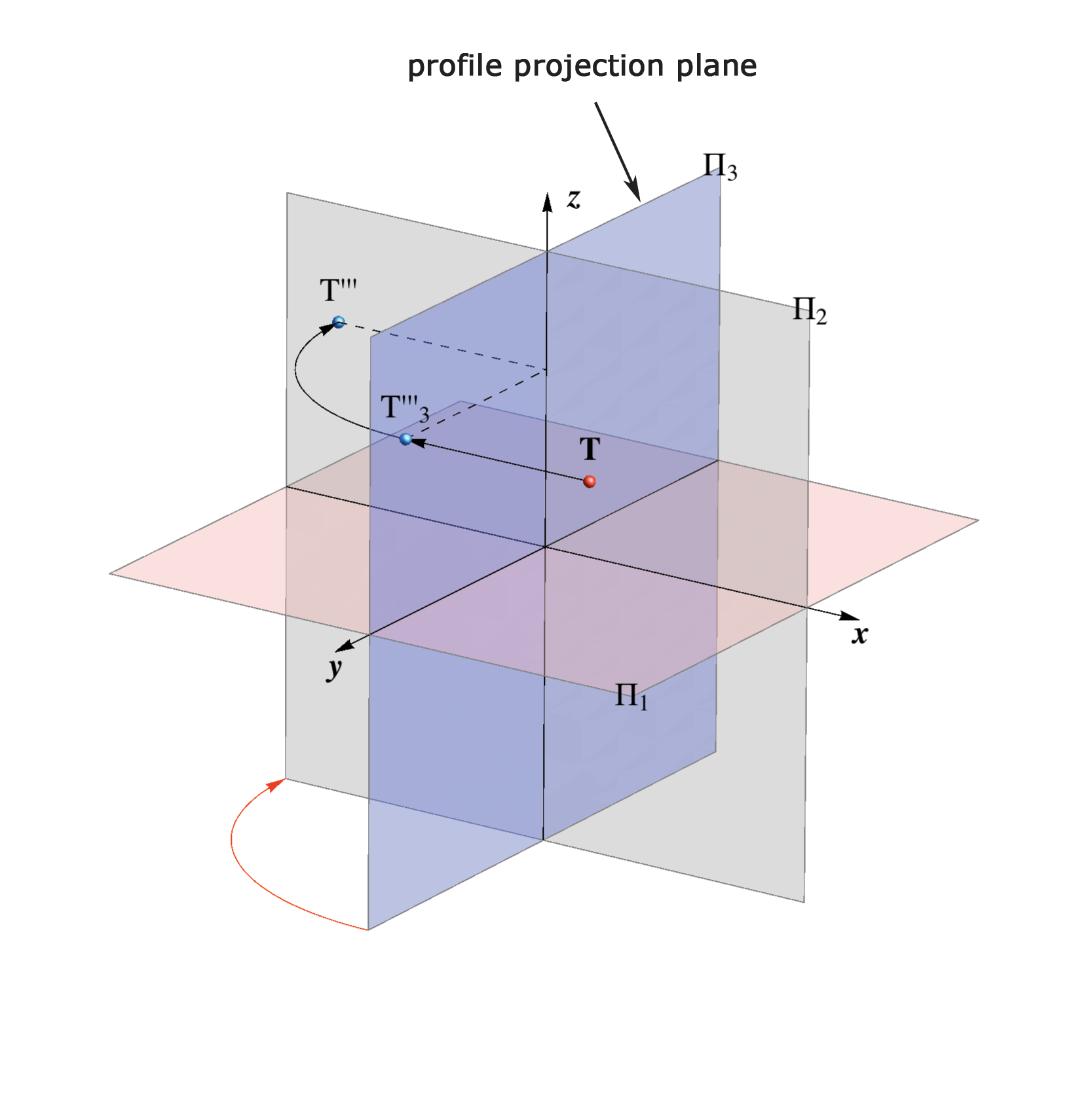
Often this line is used as a point of reference on engineering drawings. Sketching generally means freehand drawing. The engineering drawings prepared by GSFC design personnel or contractors on GSFC. Reference plane is used by engineers to show their projection of objects and the plane on which the projection of objects like points lines planes solids projects called plane of projectionin practice Orthographic projection uses two principal planes ie horizontal plane HP and vertical plane VP.

Source Image @ unacademy.com

Source Image @ www.flight-mechanic.com

Source Image @ www.youtube.com

Source Image @ www.youtube.com

Source Image @ www.joshuanava.biz

Source Image @ slidetodoc.com

Source Image @ www.learnpick.in
Source Image @ www.grad.hr
Source Image @ civilseek.com
If you are searching for Drawing Plane Definition Engineering you've reached the ideal place. We have 10 images about drawing plane definition engineering including pictures, pictures, photos, backgrounds, and more. In these page, we also have number of graphics out there. Such as png, jpg, animated gifs, pic art, logo, blackandwhite, translucent, etc.
If the posting of this site is beneficial to your suport by spreading article posts of the site to social media marketing accounts that you have got such as Facebook, Instagram and others or may also bookmark this blog page while using title Orthographic Projection Drawing A Comprehensive Guide Work with Ctrl + D for laptop devices with House windows operating-system or Order + D for laptop devices with operating system from Apple. If you are using a smartphone, you can also utilize the drawer menu with the browser you use. Be it a Windows, Mac pc, iOs or Android operating-system, you'll still be able to download images using the download button.
0 comments:
Post a Comment